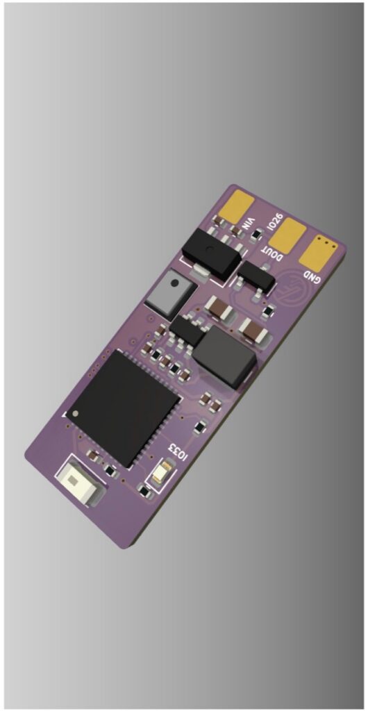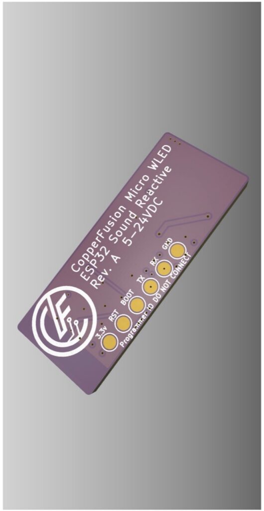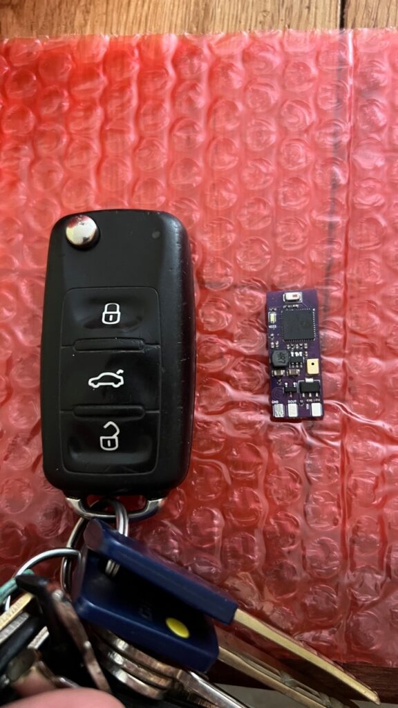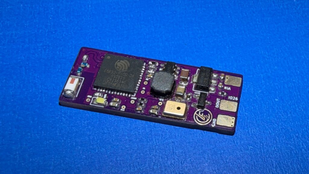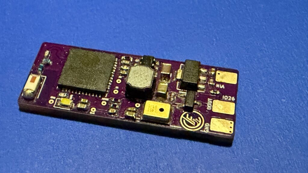
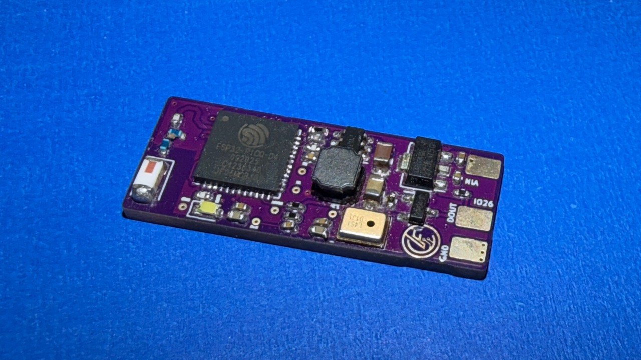
I designed this compact WLED controller to fit inside aluminium LED profile intended for 12 mm LED strip. The aim was to keep the controller hidden alongside the strip while still providing an ESP32-based platform capable of running sound-reactive WLED.
Revision one
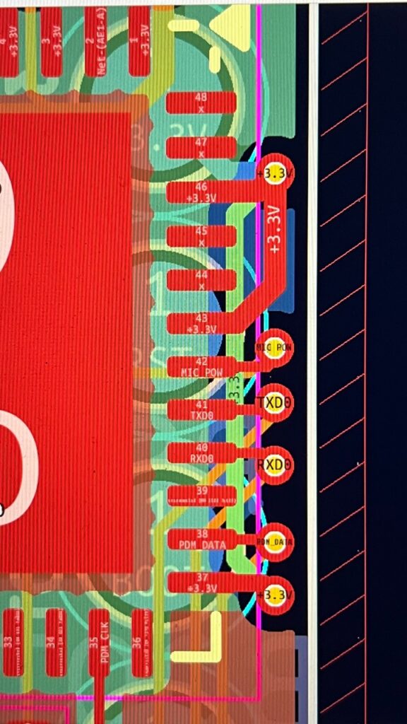
The first assembled boards exposed two separate design mistakes. The first was in the ESP32-PICO-D4 power connections: I had missed several pads that needed to be connected to the 3.3 V rail. The chip received enough power to show signs of life, but not enough to start correctly for flashing and normal operation.
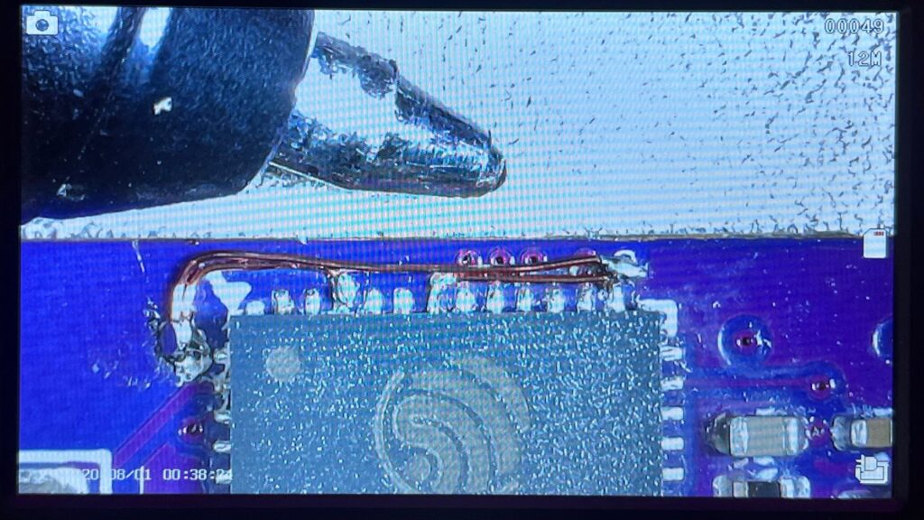
I recovered the board by adding fine enamelled-wire links between the missing 3.3 V pads. With those connections in place, the ESP32 powered correctly and I was able to flash the sound-reactive WLED firmware.
Finding the RF fault
Getting the firmware running revealed the second issue. I had misread the chip-antenna requirements and omitted the passive matching components needed between the ESP32 radio and the antenna. The result was extremely unreliable Wi-Fi: the controller would either fail to connect or repeatedly drop its connection.
This was a useful reminder that a PCB can be electrically functional while still failing at RF. Antenna layout and matching need to be treated as part of the circuit rather than as an optional detail added at the end.
Programming fixture
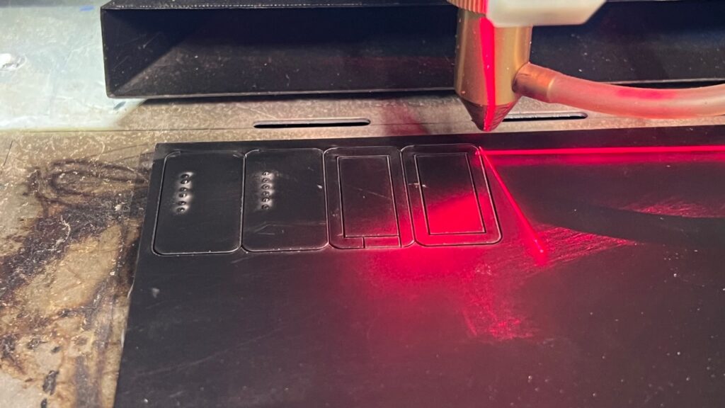
To make revision-one boards easier to flash, I laser-cut an acrylic mount for a pogo-pin programming fixture. The fixture aligns the board’s programming pads with my ESP32 burner board, avoiding the need to solder temporary programming wires to every controller.
Revision two moves the programming pads to the component side of the PCB, so the original acrylic mount no longer matches the board. A new pogo-pin arrangement will be made for the revised pad positions before batch programming.
Revision two
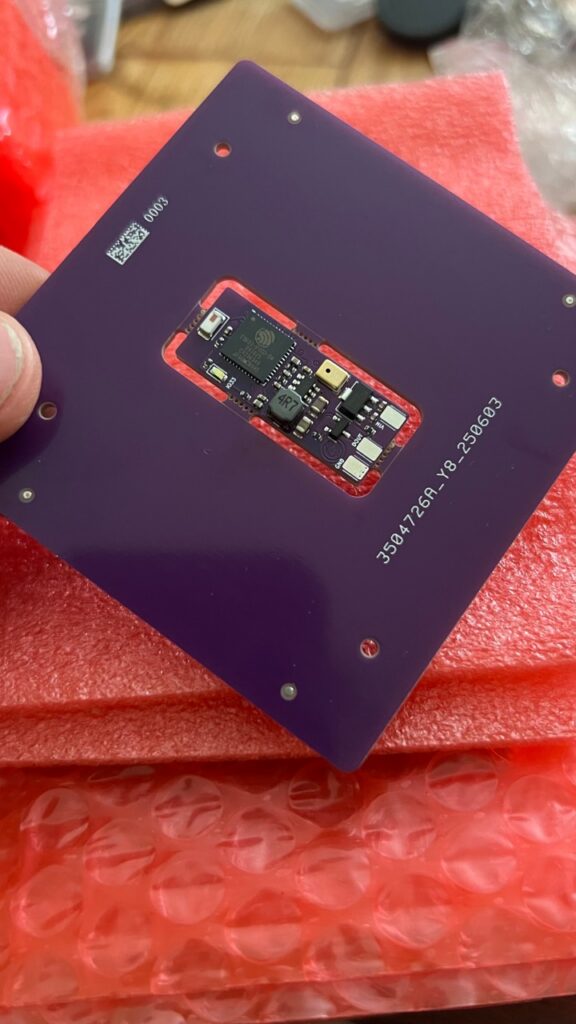
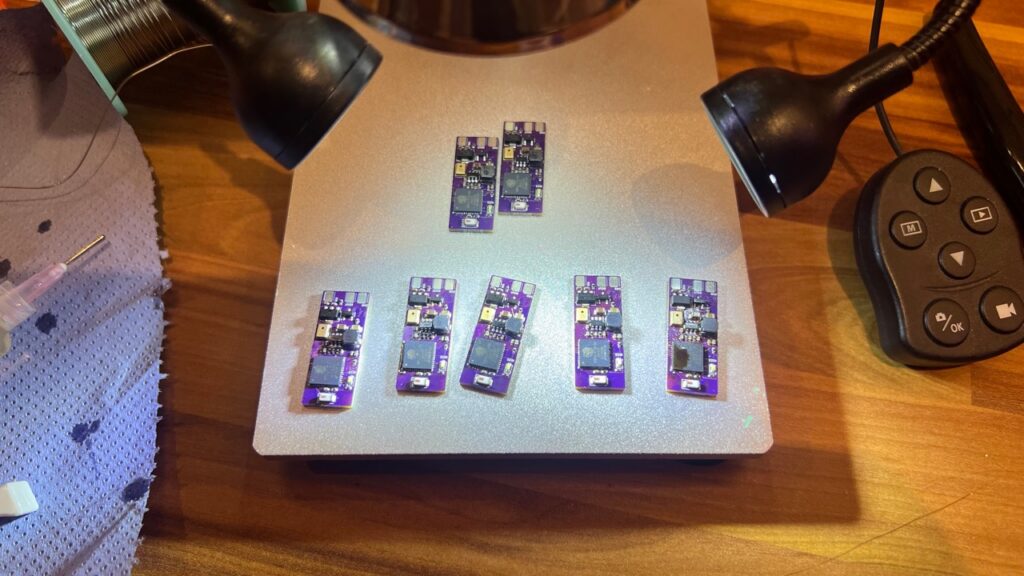
The revision-two PCB corrects both known design problems: the ESP32-PICO-D4 power connections are complete and the required antenna matching network has been added. A revision-two board has now been assembled, but it has not yet been powered, flashed or tested for Wi-Fi performance. Those validation results will be added after bench testing.
The gallery includes revision-one renders and debugging work, fabrication of the revision-one programming fixture, and the assembled revision-two board.