Aeolus is the climate controller I am developing for my home data cabinet. It combines distributed temperature and humidity sensing, closed-loop fan monitoring, local displays and a Web interface in a controller intended to fit behind a 1U rack blanking plate.
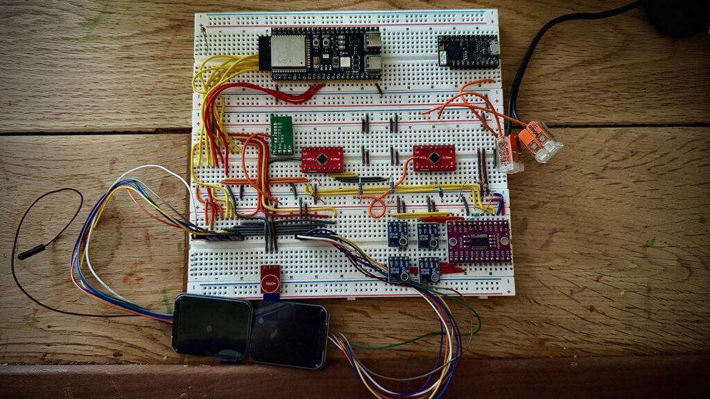
The project is currently running as a breadboard prototype. With Codex helping me implement and iterate the firmware, it can now read the cabinet sensors and control fan speed in response to temperature. The final electronics are being divided into purpose-built power and control PCBs.
Measuring the cabinet
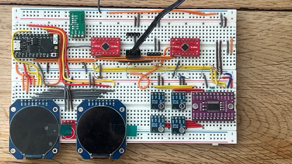
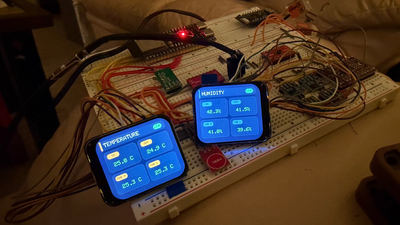
A TCA9548A I²C multiplexer allows Aeolus to support up to eight SHT21 temperature and humidity sensors without address conflicts. Four positions are currently central to the design: cabinet air inlet, air outlet, and the upper and lower areas at the front of the cabinet. The front upper and lower readings currently provide the temperature input used to determine fan demand.
The additional multiplexer channels leave room to monitor more equipment zones later without redesigning the controller.
Fan control and protection
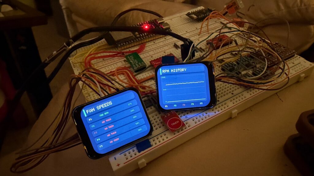
The main fan board is based around an EMC2305, providing five independently monitored fan channels with PWM control and tachometer feedback. The firmware reports commanded drive, measured RPM and stopped or missing-tach conditions rather than treating the fans as open-loop loads.
A future daughter board can add another EMC2305, allowing the design to expand beyond the five channels on the main power PCB. The board architecture keeps that expansion optional.
Aeolus will also connect to my Loxone home-automation system. When the house enters night mode, Loxone can request quieter fan operation to reduce cabinet noise. Temperature protection remains authoritative: if the cabinet becomes too hot, Aeolus can override the quiet request, increase airflow and only return to the lower night-time duty after the equipment has cooled.
From round displays to a 1U control panel
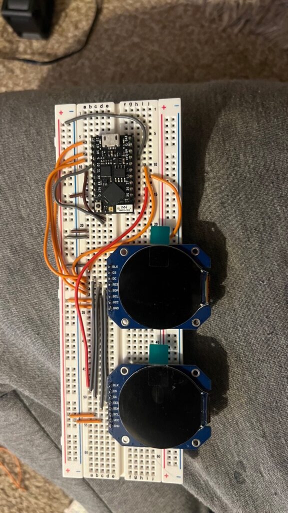
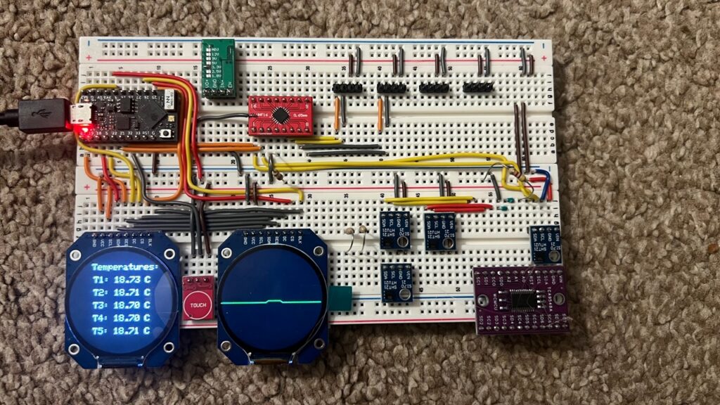
The first display experiments used two round LCD modules driven from a small ESP32 board. That prototype proved the dual-display concept and developed into an early working interface, but the physical format was not ideal for the finished rack panel.
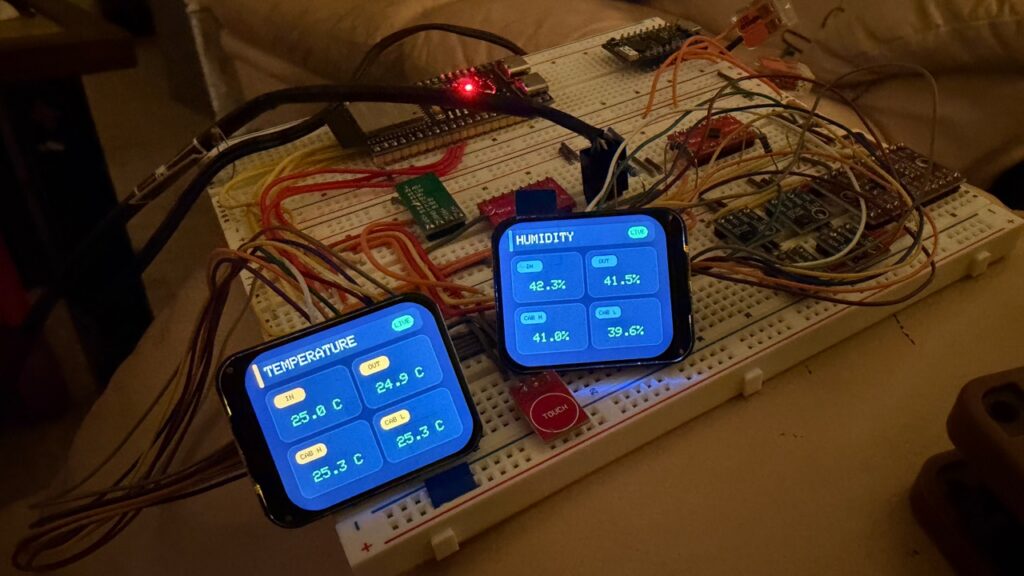
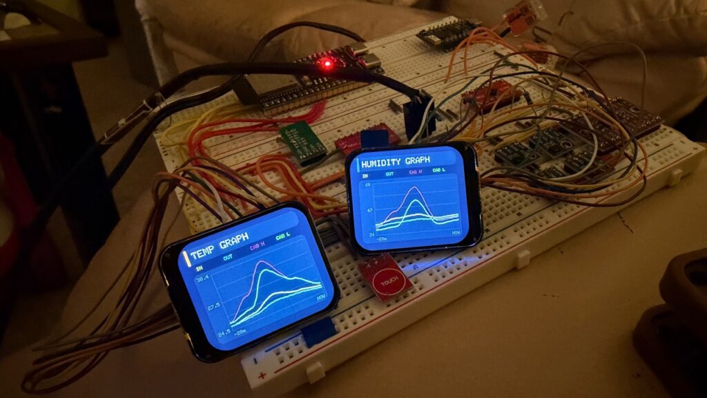
The current prototype uses two rounded-corner square displays. They make better use of the height available in a 1U blanking plate and provide more practical space for live temperature and humidity cards, history graphs, fan RPM, network state and system information. WS2812 addressable pixels are also planned for local status indication.
Split-board hardware
The final hardware is being designed as two connected assemblies:
- Power, fan and sensor board: 12 V input, power conversion, the main EMC2305, TCA9548A multiplexer, fan connections, SHT21 sensor connections and expansion headers for additional EMC2305 boards.
- Control and display board: ESP32-S3, both displays, local controls and WS2812 status pixels.
A cable between the boards keeps the higher-current fan wiring on the power board while allowing the control/display assembly to mount cleanly behind the front panel.
Local Web interface and API
The ESP32-S3 hosts a responsive local Web interface for current conditions, historical temperature and humidity graphs, fan configuration, live RPM and system information. The interface also exposes an API so temperatures, humidity readings, fan speeds and controller state can be integrated into other devices and automation systems.
The controller is designed to keep its local sensing and cooling logic operating even if another system or the network is unavailable.
Current state
The breadboard system has working sensor acquisition, display pages, Web monitoring and temperature-responsive fan control. The next hardware stage is completing the main power/fan/sensor PCB and the ESP32-S3 control/display PCB, followed by integration into the 1U rack panel and testing in the cabinet.